Leave Your Message
-
Phone
-
E-mail
-
Whatsapp
-
Wechat

Why Choose a Fuse Cutout Isolator for Global Power Systems?
A Fuse Cutout Isolator combines overcurrent protection with a visible, practical isolation point. That combination matters on rural feeders, transformer banks, and industrial distribution lines. When a fault occurs, the fuse link interrupts the circuit. The cutout then gives maintenance crews a clear physical gap. They can see the device status from ground level, depending on the installation design.
John D. McDonald, an IEEE Fellow and power-system protection specialist, states a useful principle: “Protection must be dependable, selective, and fast.” A Fuse Cutout Isolator supports that principle when engineers coordinate its fuse rating with upstream relays and downstream equipment. The device must also match system voltage, fault current, insulation level, and environmental conditions. Salt spray, dust, altitude, ice, and ultraviolet exposure can change performance. Small details matter.
Field experience often reveals the difference.
A correctly selected unit can reduce transformer damage and shorten outage work. Its simple construction may also support easier inspection in remote locations. However, simplicity can create false confidence. A poorly rated fuse, weak contact pressure, or neglected operating handle can undermine the whole arrangement. That point deserves more attention.
This article examines why utilities and industrial users choose Fuse Cutout Isolators across different power networks. It considers safety, maintenance, cost, coordination, and regional installation demands. Local standards and qualified engineering review remain essential. No single device fits every network, but this solution can offer a balanced and proven choice.
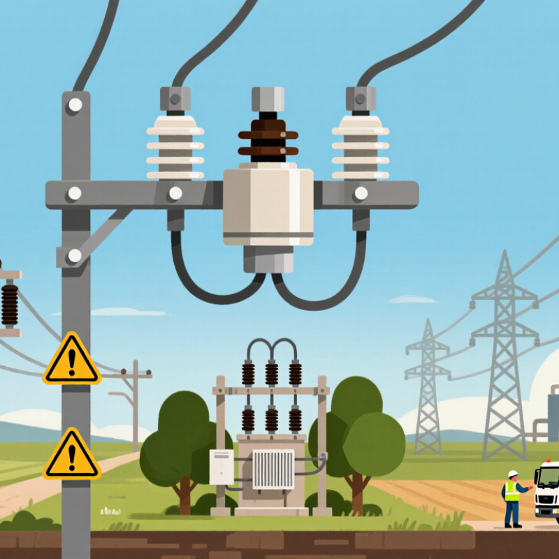
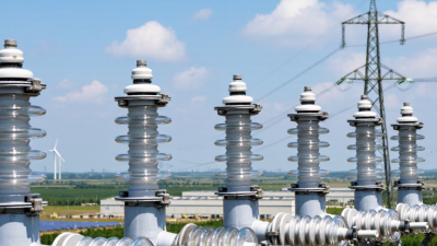
In medium-voltage distribution, fuse cutout isolators protect transformers, feeders, and rural lines from damaging faults. Rated from 12 to 36 kV, they combine fault interruption with visible circuit isolation. The fuse link opens when excessive current creates heat. The cutout then drops away, leaving a clear separation point.
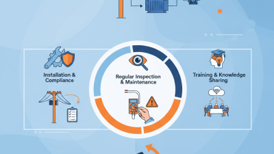
This visible gap matters during maintenance. However, it does not prove a circuit is safe by itself. Crews must verify de-energization, apply grounding, and follow approved operating procedures. Field inspections often reveal loose contacts, cracked insulation, corrosion, or incorrect fuse ratings. Small defects can become serious during rain, salt fog, or heavy switching.
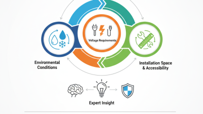
A reliable design considers short-circuit current, insulation coordination, creepage distance, altitude, wind, ice, and ultraviolet exposure. Outdoor units should also match local utility specifications and applicable technical standards. Coordination with upstream reclosers and downstream protection helps prevent unnecessary outages. At 36 kV, mechanical alignment and impulse withstand deserve particular attention. One practical weakness remains: installation quality can undermine excellent equipment. A correctly selected isolator still needs clean contacts, secure hardware, and periodic inspection.
| Evaluation Dimension | Typical Specification or Data | Why It Matters in Global Power Systems |
|---|---|---|
| Primary Function | Combined switching, visible isolation, and current-limiting fuse protection | Provides a practical protection and isolation point for medium-voltage feeders, transformers, and capacitor banks. |
| Rated Voltage Classes | 12 kV, 17.5 kV, 24 kV, and 36 kV class equipment are commonly specified | Covers widely used medium-voltage distribution networks while allowing selection for different system operating voltages. |
| Typical System Application | Overhead distribution lines, pole-mounted transformers, compact substations, and industrial service points | The open-air arrangement is suitable for locations where simple access, visual indication, and economical installation are required. |
| Continuous Current Rating | Common device ratings include 100 A, 200 A, and 400 A; the fuse-link rating is selected separately | Separating the cutout rating from the fuse-link rating supports coordination with transformer load current and feeder protection. |
| Short-Circuit Protection | High-interrupting-capacity fuse links can clear prospective fault currents within their certified rating | Fast fault clearing limits thermal and mechanical stress on transformers, conductors, and connected equipment. |
| Isolation Visibility | The fuse carrier or dropout tube provides a visible open position when correctly installed | Visible separation supports safe inspection and maintenance procedures, subject to local operating rules. |
| Operating Mechanism | Manual hook-stick operation is common; some designs include load-break or remote-operation accessories | Manual operation can reduce control-system complexity, while accessories can improve operational flexibility. |
| Load-Break Capability | Available only where the complete device is specifically rated for load interruption | A standard expulsion fuse cutout must not be used to interrupt load current unless its certified duty includes load breaking. |
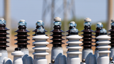
| Insulation Options | Porcelain or polymeric housings; polymeric designs generally offer lower mass and improved contamination performance | The insulation material influences weight, pollution performance, mechanical strength, and maintenance requirements. |
| Environmental Suitability | Outdoor units are selected for humidity, ultraviolet exposure, pollution, wind, and temperature conditions defined by the project | Environmental verification helps maintain insulation strength and mechanical performance over the service life. |
| Standards and Testing | Applicable requirements may include IEC 62271-103, IEC 62271-105, IEC 60282-1, or equivalent national standards | The applicable standard depends on the device construction, switching function, fuse-link type, and installation country. |
| Protection Coordination | Fuse time-current characteristics should be coordinated with transformer inrush, full-load current, downstream devices, and upstream protection | Correct coordination reduces nuisance operation while ensuring faults are cleared selectively and rapidly. |
| Main Advantages | Compact construction, low installation complexity, visible isolation, and economical fault protection | These characteristics make fuse cutout isolators suitable for many rural, utility, renewable-energy, and industrial medium-voltage installations. |
Note: Ratings are typical selection ranges rather than a universal product specification. Final selection must be based on the system voltage, available fault current, insulation level, environmental conditions, fuse-link characteristics, and applicable local standards.