Leave Your Message

Why Choose a Shackle Isolator for Power Systems?

Why Choose a Shackle Isolator for Power Systems?

A Shackle Isolator supports reliable insulation in compact low- and medium-voltage distribution networks. Its shape suits poles, terminal points, and tight overhead arrangements. The design is simple, but simplicity demands careful selection. Engineers must check voltage class, mechanical loading, creepage distance, pollution severity, and conductor compatibility.

Dr. William H. Kersting, a respected power-distribution engineer, states, “Distribution equipment must perform safely during both normal and abnormal conditions.” This principle explains the value of a properly specified Shackle Isolator. During field work, technicians may see porcelain surfaces exposed to rain, dust, salt, and bird contamination. A suitable isolator helps maintain electrical clearance and supports stable conductor positioning. Its compact profile can also reduce installation complexity on crowded poles.

The choice is not automatically correct.

A polymer unit may reduce weight and resist breakage during handling. A porcelain unit may offer familiar performance and strong resistance to ultraviolet exposure. Neither option should be selected by habit alone. Real service conditions matter more than appearance. Inspection records, torque checks, surface damage, and mounting alignment provide practical evidence. Small cracks or loose fittings can become serious weaknesses during storms.

This article examines how a Shackle Isolator supports safety, durability, and maintenance efficiency. It also considers its limitations, because no component solves every distribution problem. Better decisions come from combining manufacturer data, applicable standards, field experience, and honest review of past failures.
Why Choose a Shackle Isolator for Power Systems?

What Is a Shackle Isolator in a Power System?

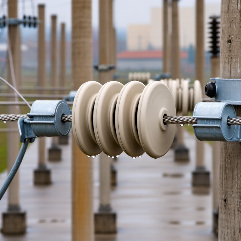
A shackle isolator is a compact isolation device used in overhead power systems. It helps separate a section of conductor from the electrical supply during inspection, maintenance, or fault investigation. The unit is commonly installed on a pole or support structure, where its insulated body and openable connection create a visible separation point.

The word “shackle” often describes the supporting insulator arrangement, but terminology varies between regions and utilities. That detail matters. Some devices only provide isolation and must not interrupt load current. Others may include switching features approved for specific operating conditions. The equipment rating, installation method, and local electrical rules must always be checked before operation.

In practical installations, technicians inspect the isolator for cracked insulation, loose hardware, corrosion, and signs of tracking. They also confirm safe clearance from nearby conductors and structures. A clear operating position is valuable during emergency work. However, a shackle isolator is not a substitute for full system isolation, testing, and grounding procedures. That limitation is easy to overlook. Poor labeling can create serious confusion, especially on older poles. Routine inspection records, accurate diagrams, and trained personnel make the device more reliable in daily power-system maintenance.
How Shackle Isolators Are Designed and Installed

A shackle isolator supports conductors while maintaining electrical separation from the mounting structure. Its compact shape suits low-voltage distribution lines, service connections, and tight installation spaces. Design starts with the system voltage, conductor size, mechanical load, and environmental conditions.

Engineers assess creepage distance and insulation strength carefully. Rain, dust, salt, and sunlight can reduce surface performance over time. Porcelain offers strong resistance to heat and weathering. Polymer materials usually reduce weight and improve impact resistance. Neither option is automatically better. Selection must match the site.

Installation begins with an approved isolation procedure and a verified dead circuit. Technicians inspect the isolator for cracks, deformation, and contamination before handling it. The mounting surface should be stable and correctly aligned. Loose hardware can create vibration, uneven loading, and eventual conductor movement. Use suitable bolts, washers, and corrosion-resistant fittings. Tighten them to the specified torque, not by guesswork.

Keep the conductor within the intended groove. Avoid sharp bends near the isolator. Check phase spacing and clearance from grounded metal. A final inspection should confirm secure fittings, clean insulation, and proper conductor tension. Small details matter. Field conditions may expose weaknesses that drawings do not show. Rechecking the design after installation can reveal an overlooked drainage issue or insufficient working clearance.

Key Electrical and Mechanical Functions

Why Choose a Shackle Isolator for Power Systems?

A shackle isolator performs two essential jobs: electrical insulation and mechanical support. It separates an energized conductor from a pole, bracket, or wall while carrying everyday loads. Its compact shape suits low-voltage distribution lines, especially where space is limited. The insulating body creates a longer leakage path, helping reduce current flow across wet or dusty surfaces. Material quality matters because heat, ultraviolet exposure, salt, and repeated temperature changes can slowly weaken insulation.

Mechanically, the isolator must resist conductor tension, vibration, wind movement, and occasional impact. A secure fixing point prevents the conductor from shifting during service. Correct hardware alignment is important. Even a strong isolator may perform poorly when bolts are overtightened or the conductor is bent sharply. During field inspections, technicians often find small cracks near mounting holes. They are easy to miss. Those cracks can grow under vibration and moisture, so visual checks should include the underside and hardware contact areas. Electrical testing alone may not reveal every mechanical problem.

Tips: Match the isolator with the system voltage, conductor size, and expected mechanical load. Check creepage distance for polluted or coastal environments. Keep contact surfaces clean and dry during installation. Do not reuse damaged units. A torque specification should guide tightening, although actual site conditions sometimes require careful judgment. Record cracks, discoloration, loose fittings, and unusual conductor movement during routine inspections. Mistakes happen, even in experienced teams. A second inspection can catch them.

Why Choose a Shackle Isolator for Power Systems? - Key Electrical and Mechanical Functions

Function or Design Dimension Typical Data or Performance Range Why It Matters in a Power System Key Selection Considerations
Primary application Low-voltage overhead distribution, service connections, and line-end or angle supports Provides an insulated support point for conductors while allowing compact installation on poles, walls, brackets, or cross-arms. Confirm the system voltage, conductor arrangement, mounting orientation, and applicable utility or national requirements.
Rated system voltage Commonly used on low-voltage systems up to approximately 1 kV; the exact rating is product- and standard-dependent Maintains electrical separation between the energized conductor and the supporting structure. Choose the insulator using the system's highest operating voltage, pollution level, altitude, and required clearances.
Insulation resistance Normally specified in the megaohm or gigohm range when dry and tested under a defined method Limits leakage current through the insulator and helps maintain circuit reliability during normal operation. Moisture, surface contamination, aging, and mechanical damage can reduce insulation resistance; use the manufacturer's test requirement.
Power-frequency withstand Typically specified as a dry and wet withstand voltage rather than as a universal value Demonstrates that the insulation can withstand temporary power-frequency overvoltages without flashover or puncture. Wet withstand performance is especially important in areas exposed to rain, fog, salt, dust, or industrial pollution.
Lightning impulse withstand Specified by the applicable design standard and insulation coordination study; not a single universal rating Improves the margin against steep-front surges caused by lightning or switching events. Coordinate the insulator level with surge arresters, conductor spacing, pole grounding, and the network's insulation level.
Creepage distance Selected according to the required specific creepage distance, typically expressed in mm/kV Reduces the risk of pollution flashover by increasing the surface path between energized and grounded parts. Use a longer or profiled creepage path for coastal, dusty, chemical, or high-humidity environments.
Air clearance Determined by system voltage, transient overvoltage, installation geometry, and local electrical rules Prevents arcing through the air between the conductor, hardware, pole, and adjacent phases. Measure the complete installed arrangement; the insulator alone does not determine the final clearance.
Mechanical working load Common low-voltage designs are often rated from several hundred newtons to a few kilonewtons, depending on construction Supports conductor tension, dead weight, wind loading, and installation forces without excessive movement or breakage. Check the specified working load, not only the ultimate breaking load, and apply the required safety factor.
Tensile and cantilever strength Must be verified for the actual loading direction; tensile and transverse loads may have different limits Maintains conductor position at line ends, corners, and intermediate supports where unbalanced forces occur. Consider span length, conductor mass, ice, wind pressure, angle deviation, and asymmetric loading.
Conductor retention Compatible with tie wires, straps, clamps, or grooves sized for the specified conductor diameter Prevents conductor slippage and controls movement caused by wind vibration or thermal expansion. Use compatible hardware and avoid excessive tightening that could damage the conductor or the insulator body.
Material options Glazed electrical porcelain or weather-resistant polymeric materials such as silicone-rubber composite designs Provides the required dielectric performance, mechanical strength, weather resistance, and service life. Porcelain offers rigidity and proven surface durability; polymeric designs can reduce weight and improve impact resistance.
Weather and pollution resistance Designed for outdoor exposure; performance depends on housing profile, glaze or polymer formulation, and pollution severity Helps the insulator withstand ultraviolet radiation, rain, temperature cycling, dust, and airborne contaminants. For severe pollution, select an appropriate creepage profile and establish an inspection or washing program where necessary.
Compact installation Small, lightweight construction suitable for close-to-pole or wall-mounted arrangements Reduces support hardware, installation space, and structural demand compared with larger distribution insulator assemblies. Verify that compact spacing still satisfies phase-to-phase and phase-to-earth clearance requirements.
Temperature capability Selected for the ambient temperature range and conductor operating temperature of the installation Maintains mechanical and dielectric performance during daily temperature changes and seasonal extremes. Account for solar heating, conductor temperature, freezing conditions, and thermal expansion of fittings.
Installation and inspection Requires correct torque, sound mounting hardware, adequate conductor restraint, and visual inspection for cracks or tracking Proper installation prevents premature failure caused by loose fittings, localized stress, contamination, or damaged surfaces. Inspect after severe weather and during scheduled line maintenance; replace units showing cracks, punctures, severe tracking, or loose fittings.
Standards and verification Verify against the applicable IEC, ANSI, national, utility, and project-specific requirements Provides a consistent basis for dielectric tests, mechanical tests, dimensions, marking, and quality control. Do not compare ratings from different standards without checking test methods, installation conditions, and declared safety factors.

Note: The values and ranges shown are representative engineering guidance for low-voltage shackle-insulator applications. Final selection must be based on the actual network voltage, environmental conditions, conductor loads, installation geometry, and the applicable product standard.

Advantages Over Other Insulator Types

In demanding power systems, a shackle isolator offers a compact solution where space and mechanical stability matter. Its shape supports conductors near poles, walls, or crossarms. Compared with pin insulators, it fits tighter layouts and handles side loads effectively. Compared with suspension strings, it needs less vertical clearance and fewer connected parts. This simpler arrangement can reduce installation time and inspection points. Field technicians often value that practicality.

Shackle isolators also perform reliably in low- and medium-voltage networks, especially where wind, vibration, and moderate contamination are concerns. Their robust body withstands routine handling during maintenance. Unlike some delicate ceramic assemblies, the enclosed form can reduce exposure to impact and moisture paths. Polymer options may offer lower weight and better pollution performance, though material quality and aging resistance require careful verification. No insulator is perfect. Selection still depends on voltage, creepage distance, temperature, and fault conditions. A rushed choice may cause leakage or premature failure.

Tips: Check creepage distance against local environmental conditions, not nominal voltage alone. Inspect mounting hardware for corrosion and correct torque. Keep conductor loading within design limits. In coastal or industrial areas, schedule visual inspections more often. Small cracks matter. When comparing insulator types, include labor, clearance, and lifecycle maintenance costs. Engineering review remains wise for unusual spans or severe contamination.

Selection and Maintenance Considerations

Why Choose a Shackle Isolator for Power Systems?

Selection and maintenance determine whether a shackle isolator remains dependable in service. Begin with system voltage, mechanical loading, conductor size, and installation geometry. A compact isolator may fit a pole well, yet fail under excessive bending or uneven hardware pressure. IEC 60815 recommends evaluating pollution severity, surface leakage distance, and site-specific contamination. Coastal salt, cement dust, and agricultural residue require different insulation margins.

Field conditions matter more than catalog appearance. EIA reliability data for 2023 recorded about 5.5 hours of average U.S. customer interruption time, including major events. Small component weaknesses can lengthen restoration work. Inspectors should check cracks, tracking marks, loose ties, corrosion, and unusual discoloration. Use calibrated torque tools. Record photographs and readings.

Maintenance should follow risk, not habit. CIGRE guidance on overhead-line insulation emphasizes inspection, contamination assessment, and coordinated design. Clean only when the procedure suits the material and operating condition. Dry brushing may spread conductive dust. That is an easy mistake. Replace units after confirmed mechanical damage, severe erosion, or failed electrical testing. Do not rely on visual inspection alone. I have seen clean-looking surfaces hide narrow cracks near fittings. Weather history, outage records, and infrared findings can improve replacement decisions. The choice should be reviewed after storms, construction changes, or pollution increases. Reliability is rarely achieved by selecting the largest insulator; it comes from matching design, installation, and disciplined inspection.